

A practical guide to crankshaft position sensor symptoms, the difference between inductive and Hall sensors, safe tests, and replacement.
My 1998 Ducati 900SS once stopped firing just after I listed it for sale. The dash lit up, the fuel pump primed, and the starter turned the engine normally, but the engine would not catch.
The fault led me to the crankshaft position sensor, also called the crank sensor, engine-speed sensor, rotation sensor, timing pickup, or CKP sensor. You have to know how the sensor in question works, because motorcycles use both passive inductive sensors and active Hall sensors, and you test them differently.
Are you obsessed with motorcycles?
Well, I am. That’s why I created this site — as an outlet. I love learning and sharing what others might find useful. If you like what you read here, and you’re a fraction as obsessed as I am, you might like to know when I’ve published more. (Check the latest for an idea of what you’ll see.)
The quick answer
A failed crankshaft position sensor can cause a crank-no-start, a sudden engine cut, intermittent stumbling, or a heat-related stall followed by a restart once the engine cools. Those symptoms also have many other causes, so test the circuit before buying a sensor.
- Start with the service manual or wiring diagram. Connector pin count alone does not identify the sensor type.
- Check fault codes and live engine speed if your motorcycle supports it. Zero rpm while the starter is clearly turning the engine points toward the sensor, wiring, air gap, or trigger wheel, but does not prove the sensor itself has failed.
- Inspect the connector and loom first. Heat, oil, corrosion, chafing, a broken conductor, or metal debris on the sensor tip can mimic a dead sensor.
- Test an inductive sensor and a Hall sensor differently. Do not apply an ohmmeter or guessed bench voltage to an unidentified sensor.
What a crankshaft position sensor does
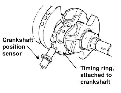
The sensor reads a trigger wheel attached to the crankshaft. Teeth, slots, or another target pass the sensor as the engine turns. A missing tooth or other reference mark lets the ECU work out crankshaft angle as well as engine speed.
The ECU uses that signal to schedule ignition and fuel injection. Many engines also use a camshaft position sensor to identify which cylinder is on its compression stroke. If the crank signal disappears, most motorcycle ECUs stop ignition and injection because they no longer know when to fire either one.
Old contact-breaker points also triggered ignition, so they are a useful historical comparison. A modern crank sensor does more: it sends speed and position information to the ECU, which calculates timing from its maps.
Passive inductive vs active Hall crank sensors
Bosch describes motorcycle crankshaft-speed sensors as either inductive or Hall sensors. Both read a rotating target without touching it, but their wiring and output signals differ.
| Detail | Passive inductive / variable-reluctance | Active Hall-effect |
|---|---|---|
| External power | No | Yes |
| Common wiring | Two signal conductors; some add a third terminal for cable shielding | Usually supply, ground, and signal |
| Output | Alternating, sine-like voltage | Digital square wave |
| Effect of cranking speed | Signal voltage rises with speed | Output level is controlled by the sensor circuit |
| Useful tests | Visual checks, manual-specified resistance, AC output, oscilloscope waveform | Supply, ground, signal switching, oscilloscope waveform |
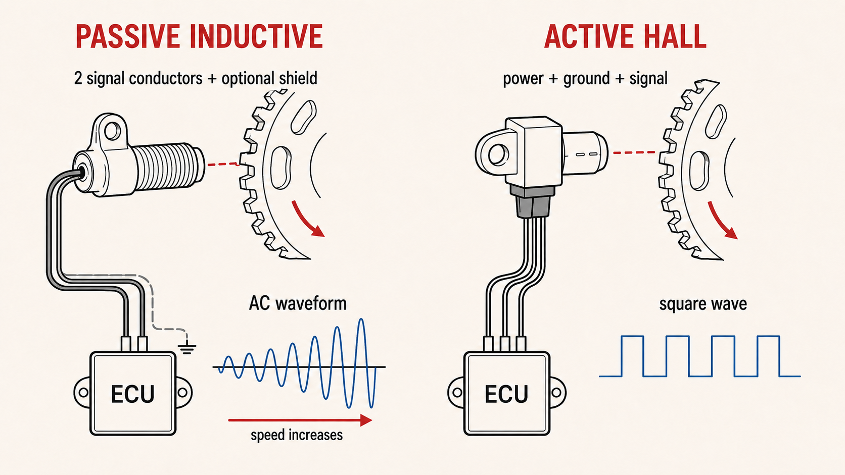
Wiring count is only a clue. The SEN8I3 on my Ducati is a three-terminal inductive sensor: two conductors carry the signal and the third connects the cable shield. Some active sensors also use two wires. Identify the system from the workshop manual, pinout, or a reliable sensor catalogue before testing it.
Symptoms of a bad crank sensor
A crank sensor fault can be complete or intermittent. Common symptoms include:
- The starter cranks but the engine does not fire. The dash and fuel-pump prime may still work normally.
- The engine cuts out suddenly. A lost crank signal can stop spark and injection together.
- The engine stalls hot and restarts cold. A winding, semiconductor, connector, or conductor may fail as it heats and recovers after cooling.
- Intermittent stumbling or an abrupt rpm drop. My Ducati stumbled around 4,000-4,200 rpm before the sensor failed more consistently.
- A crank-sensor fault code or zero live rpm during cranking. Exact codes and data access vary by motorcycle.
These symptoms do not isolate the crank sensor. A weak battery, excessive voltage drop while cranking, side-stand or clutch interlock, immobiliser, wiring fault, ignition coil, injector power supply, fuel-pressure problem, ECU relay, or damaged trigger wheel can produce similar results. A bad oxygen sensor usually does not cause a cold crank-no-start because the ECU starts in open-loop control; see the guide to open-loop and closed-loop fuel injection.
Checks to make before using a multimeter
Separate “no crank” from “cranks but will not fire.” A crank sensor cannot stop the starter motor from turning on most motorcycles. If the starter does nothing, start with the battery, fuses, switches, relays, solenoid, starter, and wiring.
- Confirm that the battery holds voltage under starter load. The guide to testing a motorcycle charging system covers the basics.
- Read stored fault codes and view live RPM during cranking if you have a compatible diagnostic tool.
- Inspect the crank-sensor connector for oil, water, green corrosion, loose terminals, and pushed-back pins.
- Follow the loom and look for chafing, tight bends, crushed sections, and damage near hot engine parts.
- Inspect the sensor tip and trigger wheel where access allows. Metal debris, a damaged tooth, excessive run-out, or an incorrect air gap can weaken or corrupt the signal.
- Check the service manual pinout and sensor specification before choosing a meter setting.
HELLA’s diagnostic guidance makes the same warning: you cannot reliably identify every sensor by appearance or terminal count, and an ohmmeter can damage an active Hall sensor if you test the wrong pins.
How to test a passive inductive crank sensor
An inductive sensor contains a magnet and coil. As a trigger tooth approaches and leaves, the changing magnetic field induces an alternating voltage. A basic multimeter can find an open winding or show AC output, but an oscilloscope gives the clearest view of signal shape, amplitude, missing-tooth reference, and electrical noise.
- Switch the ignition off and unplug the sensor. Use the wiring diagram to identify the two signal conductors. Do not count a shield or drain terminal as a third signal wire.
- Measure resistance only against the workshop-manual specification. An open circuit or near-short usually shows a failed winding or lead. A plausible resistance does not prove that the sensor works under heat and vibration.
- Check each signal conductor for an unwanted short to ground if the manual calls for this test. Account for any intentional shield connection.
- Measure output while cranking. Set the meter to low AC voltage and connect across the two signal conductors, or use an oscilloscope. Compare the result with the motorcycle’s specification. Signal amplitude depends on cranking speed, air gap, sensor design, and meter response, so a universal voltage threshold is not reliable.
- Repeat the test hot if the fault only appears hot. Test as soon as the engine stalls, then compare the reading after it cools.
Moving a steel object past a removed inductive sensor may produce a small voltage, but this bench check is weak evidence. It does not reproduce the correct air gap, trigger speed, wiring load, heat, or vibration. Testing the installed sensor while cranking is more useful.
How to test an active Hall crank sensor
A Hall sensor needs power and ground and sends a switched digital signal. Test it in the circuit with the correct pinout. Do not guess the supply voltage, and do not use resistance mode on an unidentified active sensor.
- Back-probe the supply and ground with the ignition on. Compare supply voltage and ground voltage drop with the manual.
- Back-probe the signal while cranking. A scope should show a square wave as the trigger teeth pass. A capable meter may show frequency or a changing average voltage, but a slow meter can hide individual pulses.
- Check the whole circuit if the signal is missing. Confirm the sensor’s supply, ground, connector tension, wiring continuity, trigger wheel, and air gap before condemning the sensor.
Some Hall outputs depend on a pull-up inside the ECU. Supplying a loose sensor from a guessed battery or 5 V source can lead to a false result or damage it. Use the manufacturer’s bench procedure if one exists.
Air gap and heat-related failures
The air gap is the distance between the sensor tip and the trigger wheel. Too much gap can weaken an inductive signal, especially at cranking speed. Too little can let the trigger wheel hit the sensor as parts move or expand.
Use the exact workshop-manual specification. My Ducati 900SS manual specifies 0.6-0.8 mm (0.024-0.031 in), but that is not a generic motorcycle setting. Some sensors use shims to set the gap; others have a fixed mounting face.
Heat can open a failing winding, increase resistance at a damaged conductor, or upset active electronics. If the motorcycle starts cold, stalls hot, and restarts after cooling, record resistance or waveform cold and immediately after the stall. Gently warming a removed sensor can help reproduce the fault, but keep open flame and uncontrolled heat away from it.
The Ducati 900SS case
On my fuel-injected 900SS, the sensor sits on the left side of the engine near the alternator and reads the engine’s timing target. Ducati lists it as sensor part 552.4.009.1A.
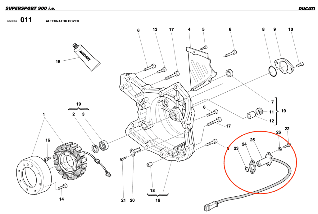
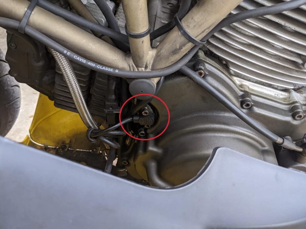
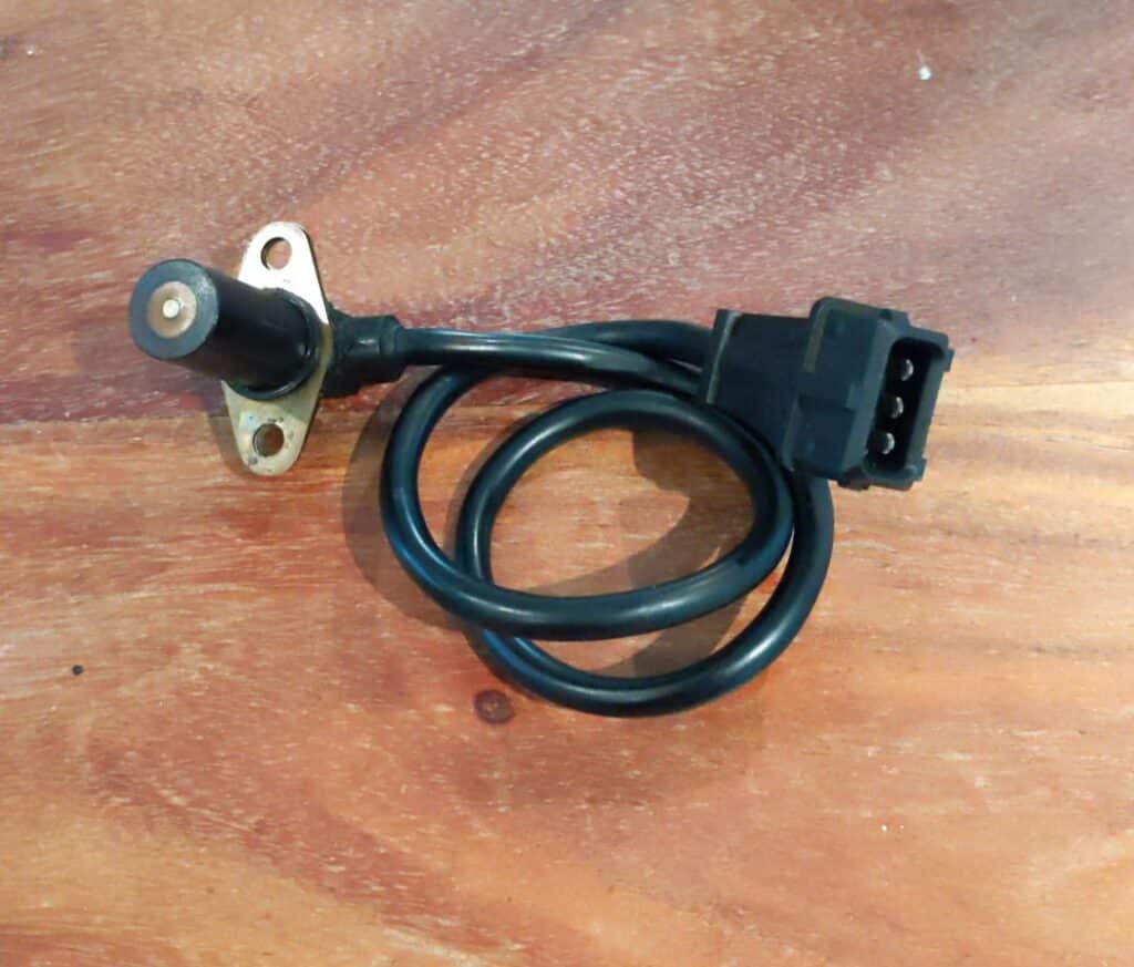
The SEN8I3 has three terminals, which originally led me to describe it as a powered Hall sensor. It is an inductive sensor with two signal conductors and a shield. Its output is an AC waveform, not a 5 V square wave. This is exactly why the wiring diagram matters more than connector count.
How to replace a crankshaft position sensor
The exact job varies by engine, but the important points are access, oil control, shims, wire routing, sealing, air gap, and fastener torque.
- Let the engine cool, disconnect the battery if the manual specifies it, and remove any bodywork needed for access.
- Check whether removing the sensor will release engine oil. Drain the oil first if the sensor sits below the oil level and the manual requires it.
- Unplug the connector and free the loom without pulling on the wires.
- Note the position and thickness of every spacer or shim before removing the mounting bolt or bolts.
- Compare the new and old sensors: mounting face, tip length, connector, lead length, sealing surface, and part number.
- Fit a new seal or O-ring where specified. Clean the mounting face and keep debris out of the opening.
- Set the air gap with the specified shims or adjustment method, then tighten the fasteners to the workshop-manual torque.
- Route the loom away from the exhaust, sharp edges, and moving parts. Reconnect it, clear any stored code if required, and confirm a stable rpm signal and normal starting.
OEM and automotive cross-references
Motorcycle manufacturers often buy sensors from automotive suppliers, so an OEM-number cross-reference can save money. Match more than the connector. The mounting pattern, nose length, air gap, lead length, sealing, pinout, sensor type, polarity, and electrical specification all have to suit the motorcycle.
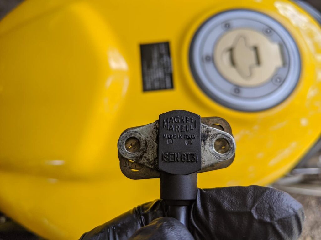
For the two-bolt Magneti Marelli SEN8I3 used on my older fuel-injected Ducati, current catalogues cross-reference Fiat 7679221, 7694335, and 60603937; Alfa Romeo/Lancia 60603937, 60810103, and 7733001; FAE 79015; Meat & Doria 87074; and Standard/Intermotor 18783. Confirm the application against Ducati 552.4.009.1A and the supplier’s current catalogue before ordering.
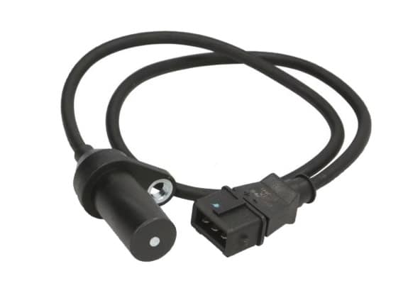
Later one-bolt Ducati sensors use different part numbers and applications. Historical automotive references include Fiat 46774532 and 55187333, but verify the exact Ducati model and current supersession rather than ordering from this number alone.
If your motorcycle cranks but has no stable crank-speed signal, work through the connector, loom, supply or winding, waveform, trigger wheel, and air gap in that order. That tells you whether you need a sensor, a wiring repair, or a mechanical correction — and avoids replacing a good part.


Hi, Well Enjoyed reading your info!, very enlightening, and interesting. Need to get some of that start your engine stuff, whats it called, something bstard sounds,like reall good stuff. Thanks, kind regards.
I’ve a ’98 Ducati 996. After warming up the bike I ride a few k’s and it cuts out. No dash, no fuel priming, no turnover, nothing. Wait 5 mins for it to cool, start it again and ride straight home. Does this sound like the crank sensor?
Sounds like bad fuel pump or clogged injector.
Hi, I am Mohammad Ali from Iran
I read your article on replacing and testing your crankshaft sensor, it was very good
I hope God gives you health and well-being
Hello Mohammad Ali. I am also from Iran and I am happy to see an acquaintance here
Do motorcycle Crankshaft sensors (2000 Triumph in particular with Sagem ECU), need to be “relearned” like many automotive applications. After replacing mine I’m unable to start my engine.
It didn’t have to on mine. Do you mean some kind of pairing? I doubt it for a bike of that vintage. By unable to start what do you mean… no turning over at all? A bad CPS on my bike meant it’d turn over but not fire.
What is the resistance in ohms of the crankshaft sensor on the triumph speed triple 955i, it shows 500 ohms to me, is it correct? The engine started fine, and after a few seconds it started to choke, to run out of fuel. And it won’t start again, measured the crankshaft sensor and it shows 500 ohms. I read somewhere that the optimal value is like 200 ohms. Greetings from Serbia
I’m sorry I’m not sure — service manual would be your friend. Per the manual, if the crankshaft sensor is faulty, you’ll get DTC P0335 when you check for fault codes. I’d take that as indication enough to replace it. Otherwise, you can do the voltage tests indicated here.
my sensor has one hole, and two wires, do you maybe know which one would be a replacement (from the car), I can’t find the value of the sensor in ohms in the manual. I read on the forums that it should be about 200 ohms, and mine shows 500. Is it your opinion that it is defective if it shows more respect. Greetings from Serbia😉
Hi. Some of the alternative ones are incorrect. Ie 2 pin Alfa Romeo one so be careful.